MSc Theses


The page provides information on the MSc Theses developed by our Master Students in Civil Engineering, under the supervision of the professors and researchers of the Structures Research Group. MSc Theses are carried out within the framework of research projects, and contrribute to the achievement of their results. For each MSc Thesis, a leaflet can be downloaded, which brifely describes its motivations and aims, methods and results, and conclusions and future developments.


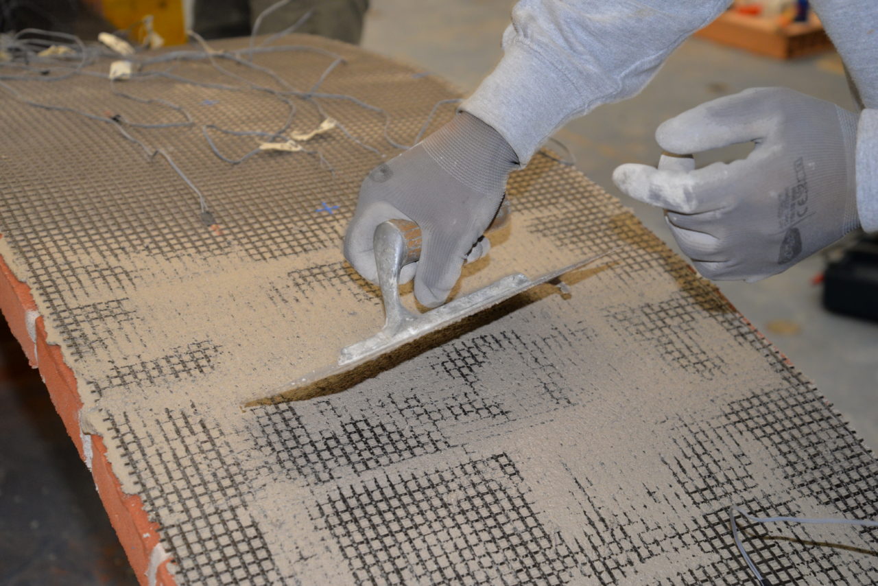
Experimental investigation on the durability of carbon and basalt FRCM composites

  • Candidate: Francesco Cittadini  
  • Supervisor: Stefano De Santis 
  • Co-supervisor: Giovanni Moretti
  • Session: October 2023
  • Download leaflet


Experimental characterization of an innovative integrated system for reinforcement and monitoring of structures

  • Candidate: Alessandro Alfieri
  • Supervisor: Stefano De Santis 
  • Co-supervisor: Giovanni Moretti
  • Session: October 2023
  • Download leaflet


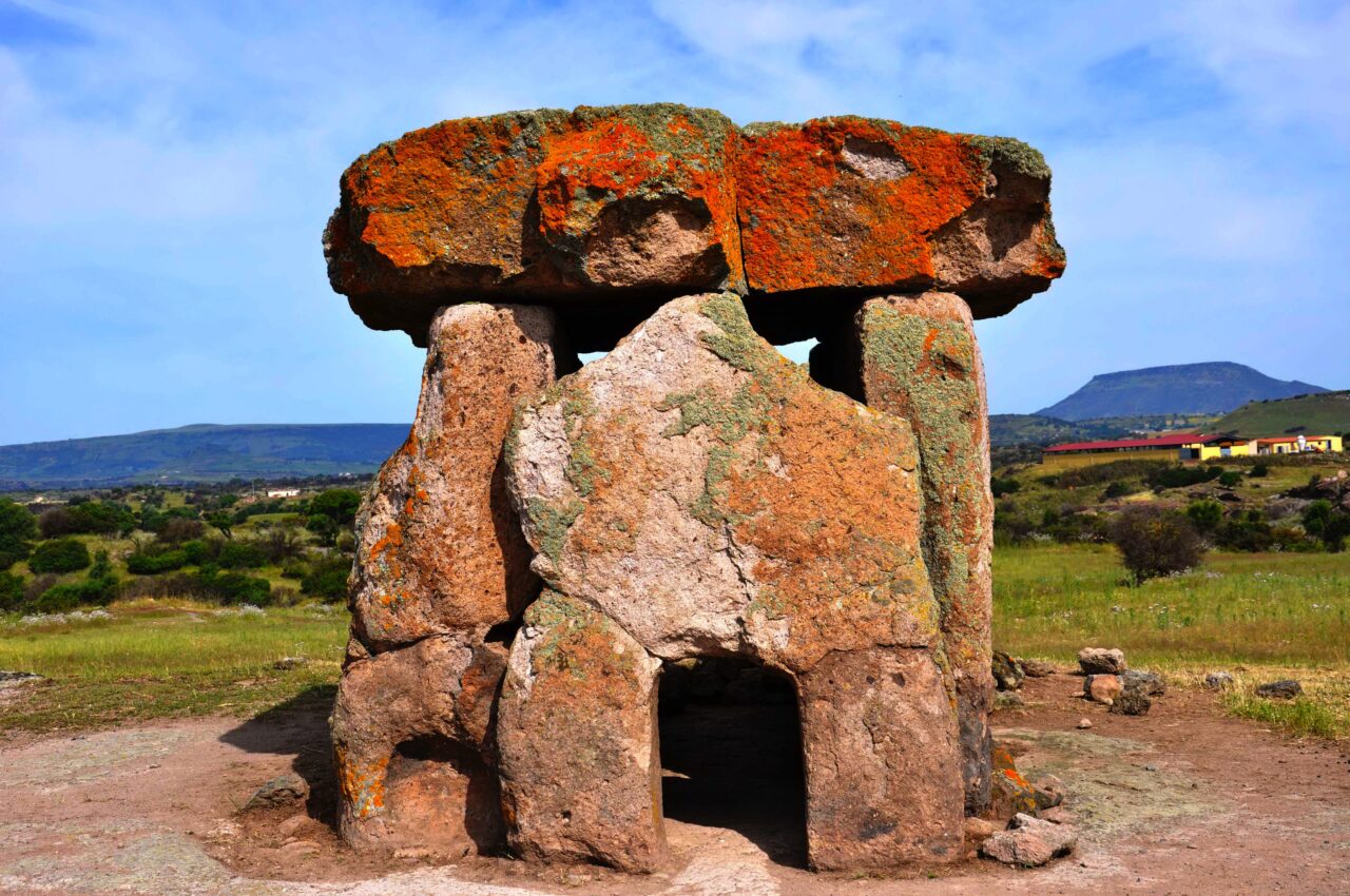
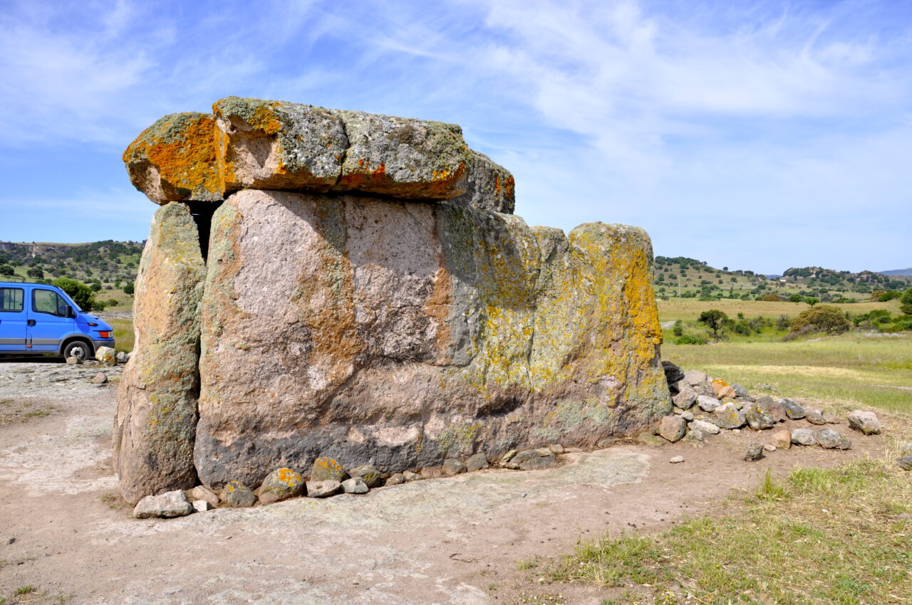
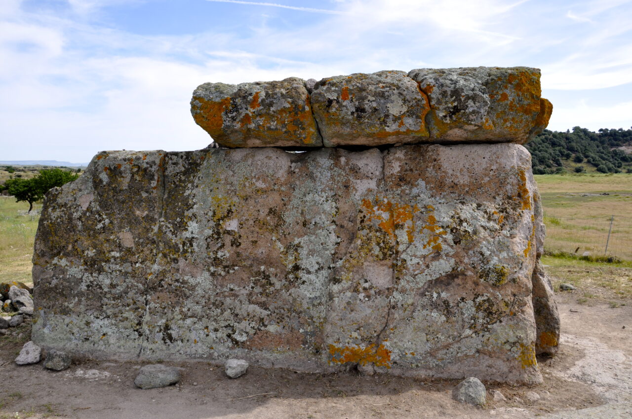
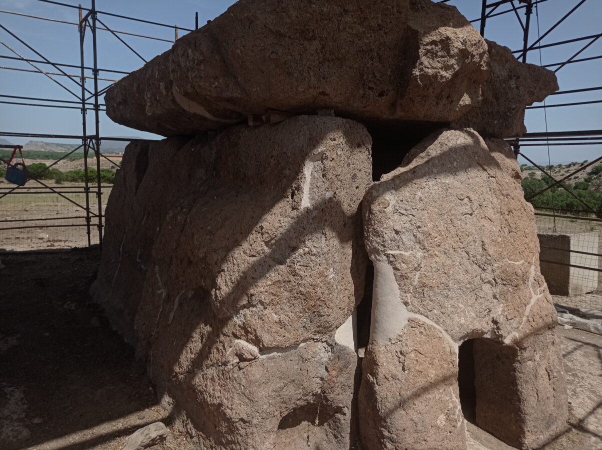
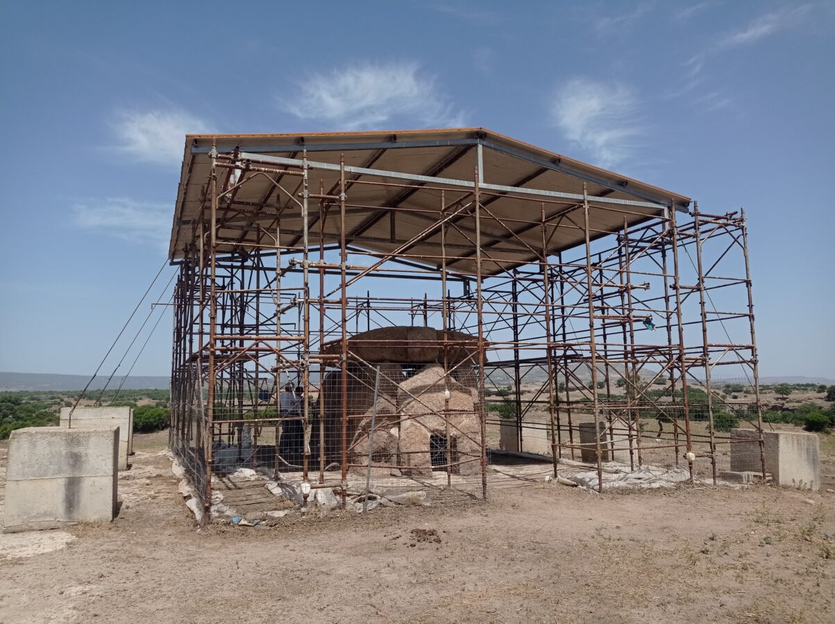
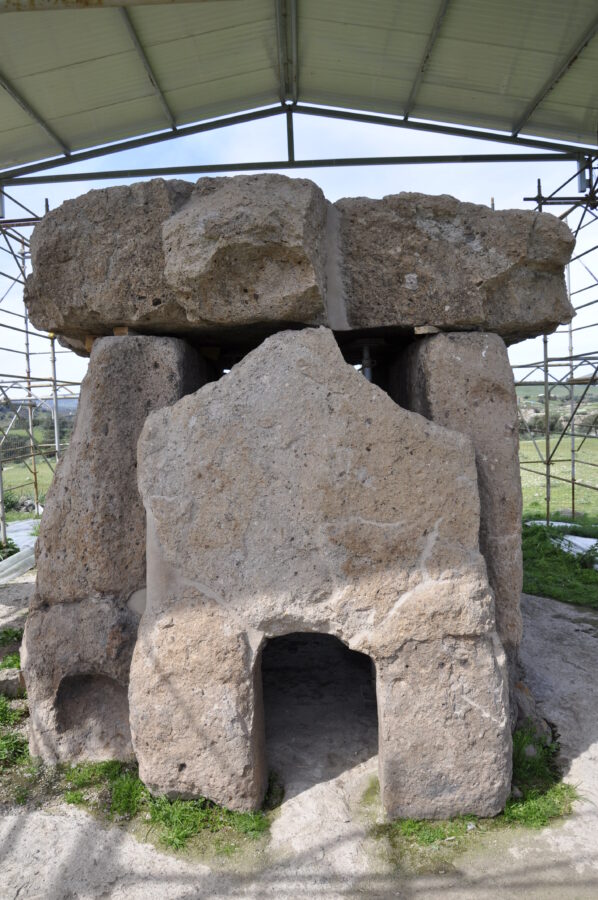
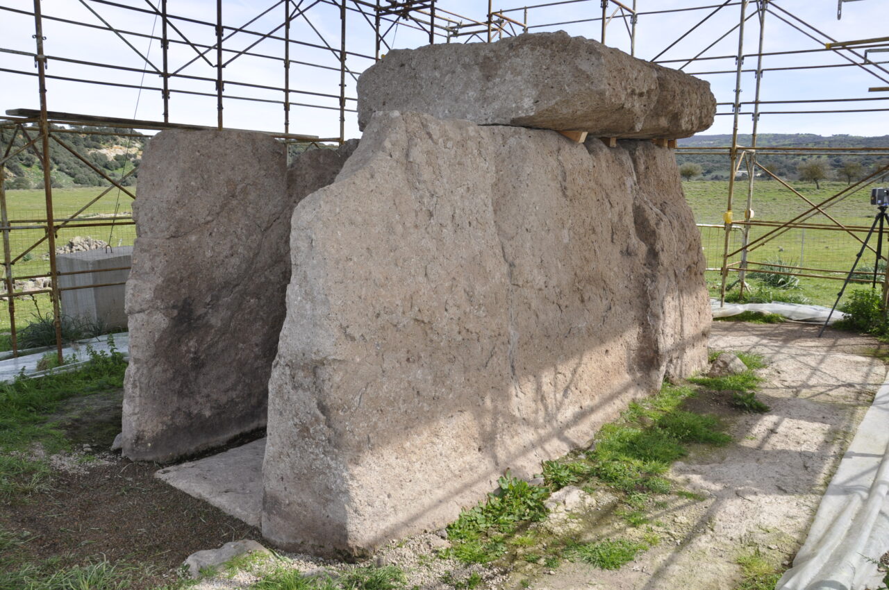
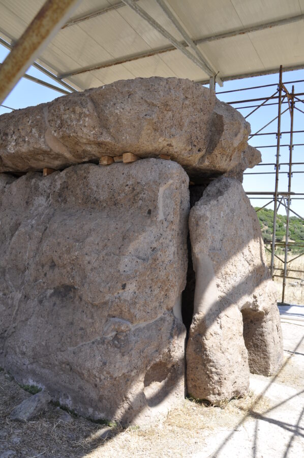
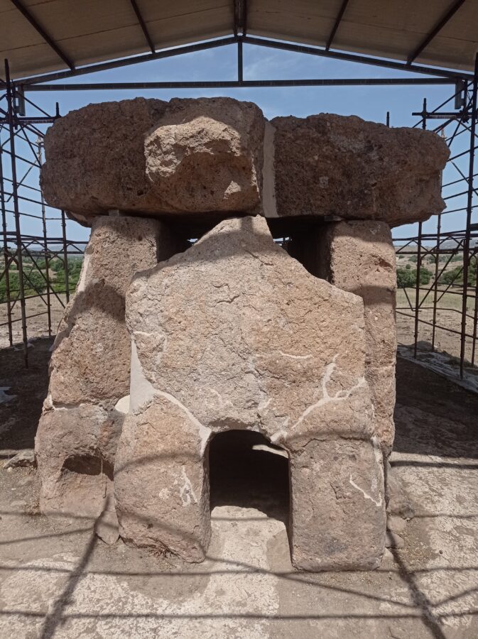
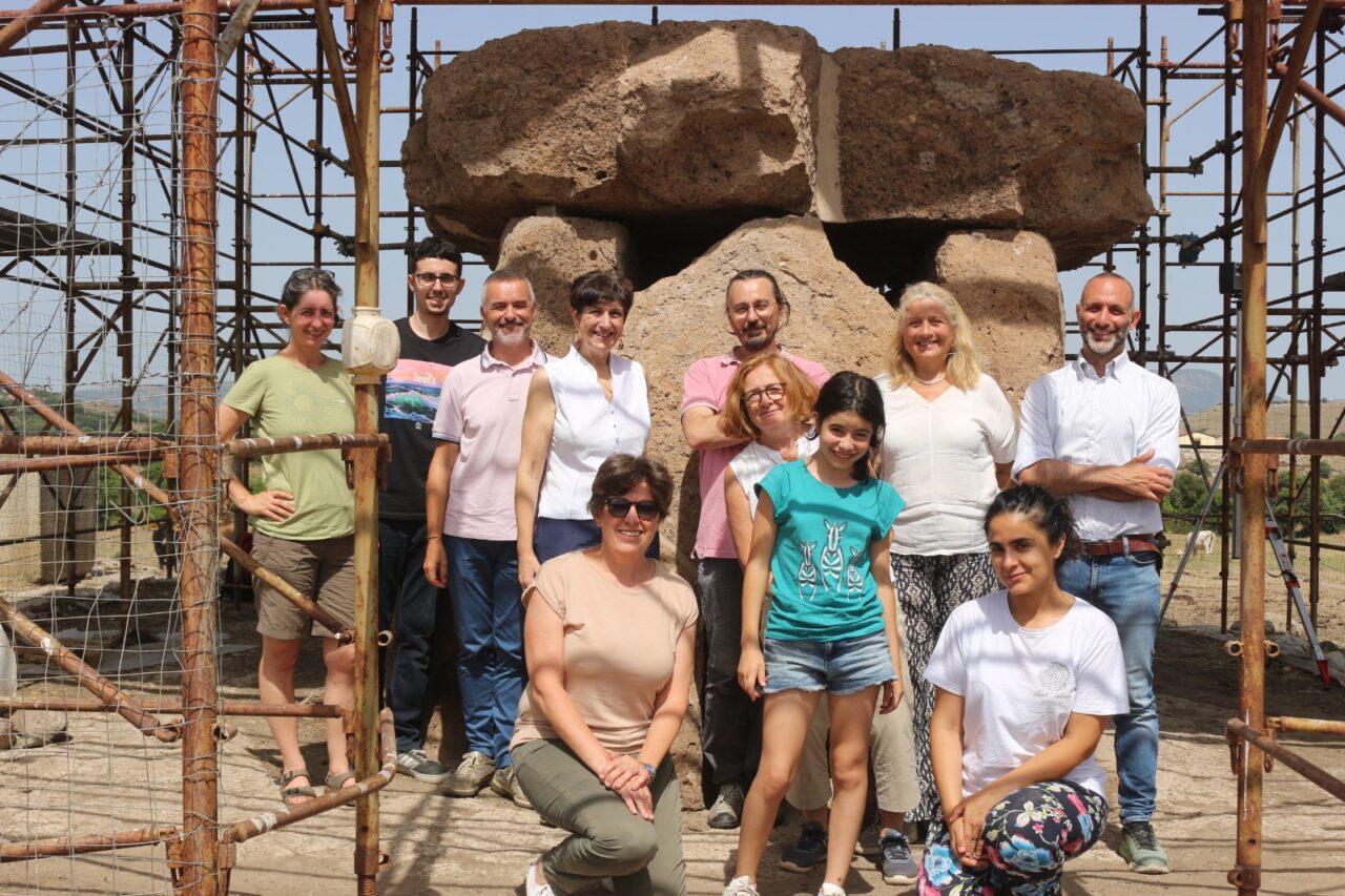
Structural assessment of Late Neolithic Sa Covaccada Dolmen in Mores (SS), Sardinia

  • Candidate: Luca Di Domenico
  • Supervisor: Stefano De Santis 
  • Session: December 2023
  • Download leaflet


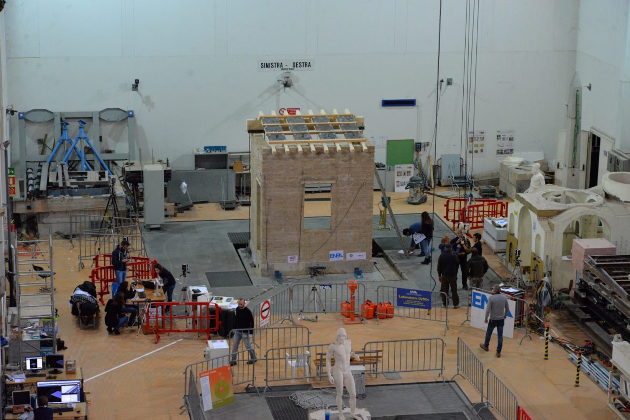
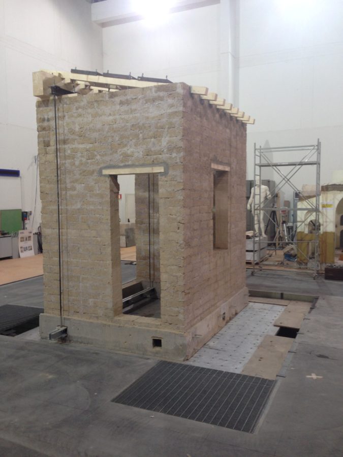
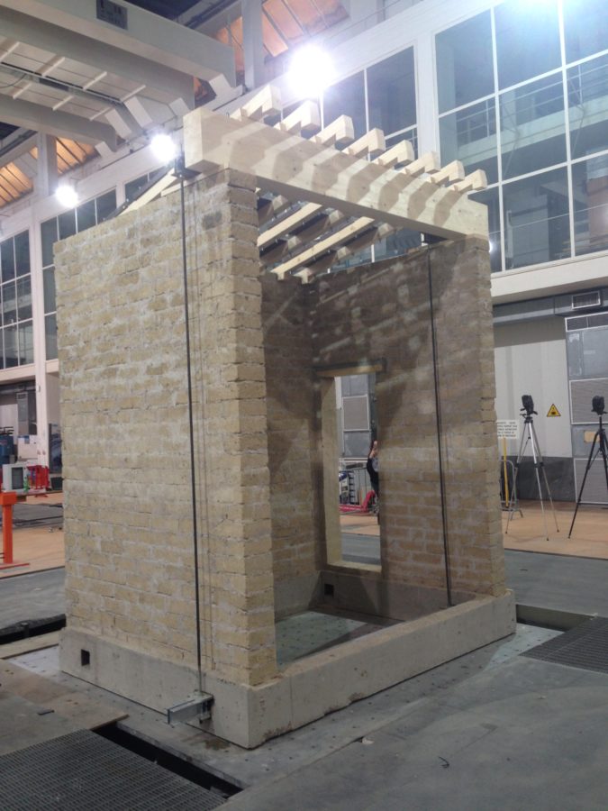
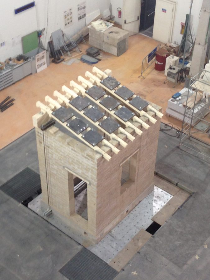
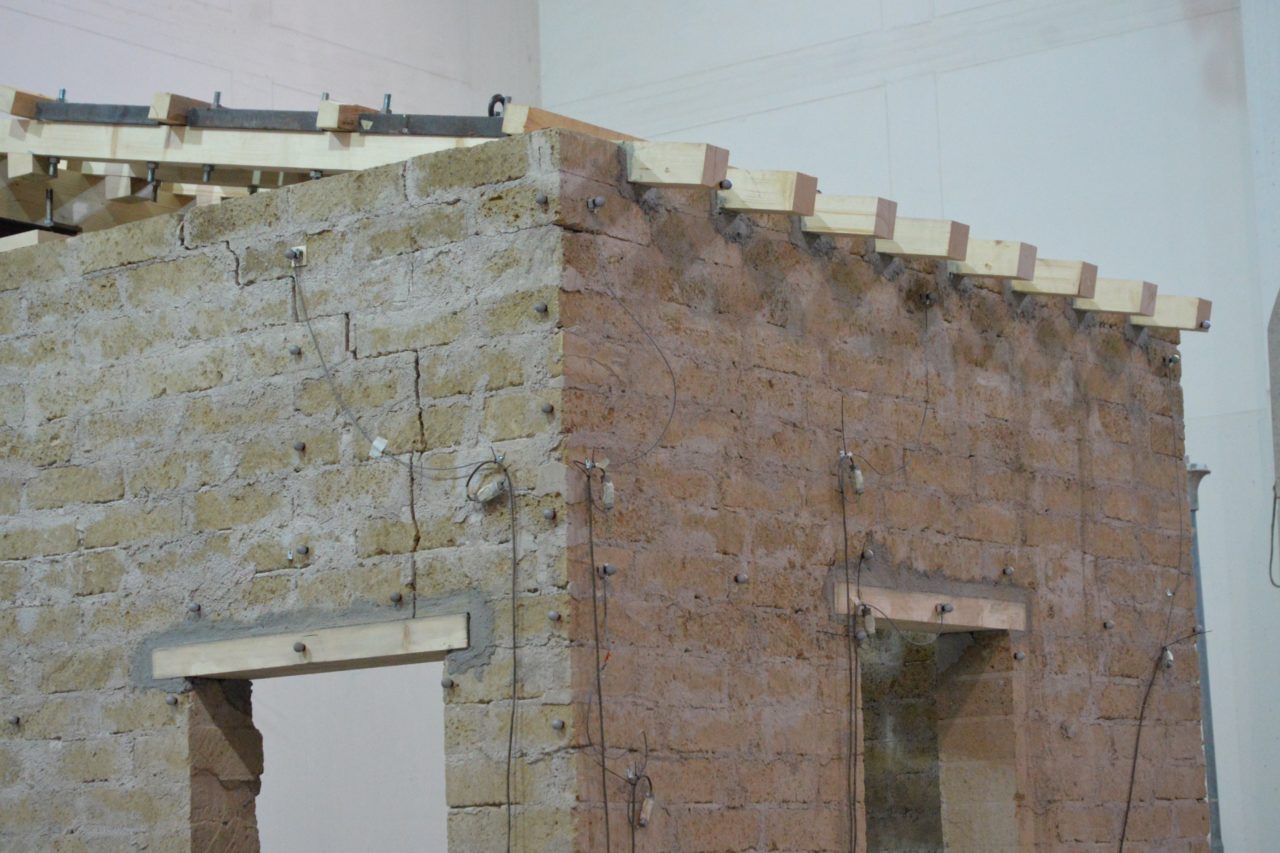
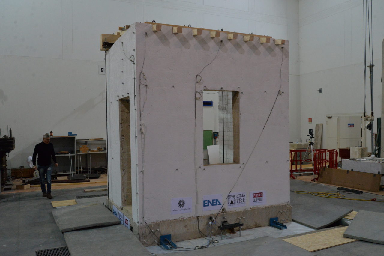
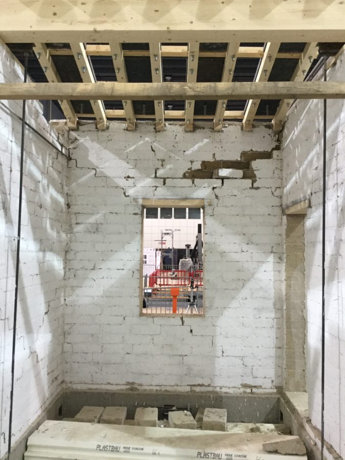
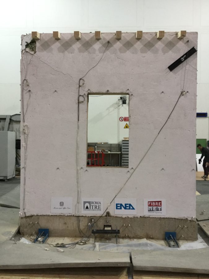
Shake table tests of a rubblestone large-scale masonry structure

  • Candidate: Jacobo Ameli
  • Supervisor: Stefano De Santis
  • Co-supervisor: Ivan Roselli (ENEA Casaccia RC)
  • Session: December 2023
  • Download leaflet


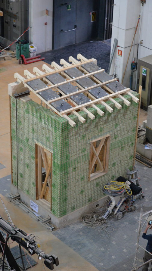
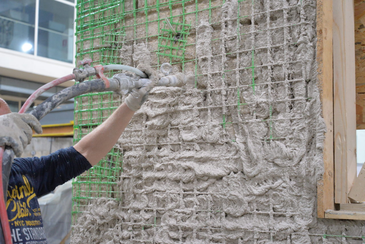
Shake table tests on a rubble stone masonry structure reinforced with UNI-CAM and RISTIL-CAM systems

  • Candidate: Flavia Del Grosso
  • Supervisor: Stefano De Santis
  • Co-supervisor: Alessandro Vari (Edil CAM Sistemi)
  • Session: March 2024
  • Download leaflet
  • The thesis was awarded the “Centro d’Eccellenza DTC Lazio Award 2024 – First Edition” in the category “Technologies for Diagnostics, Conservation, and Restoration.” link to the webpage


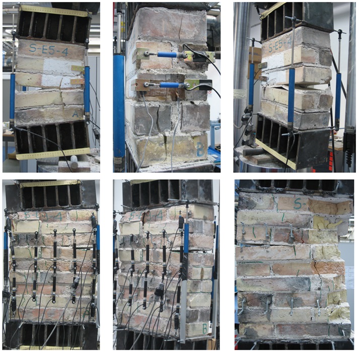
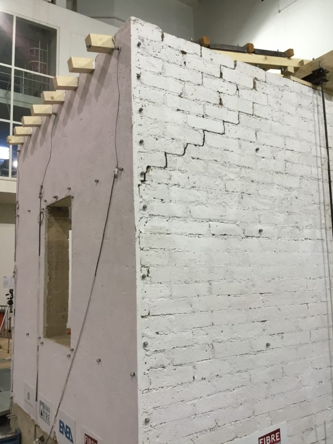
Sheppard tests on fair-face stone masonry panels with seismic reinforcements derived from Active Confinement of Masonry (CAM)

  • Candidate: Gabriele Pomponio
  • Supervisor: Stefano De Santis
  • Co-supervisor: Ivan Roselli (ENEA Casaccia RC)
  • Session: March 2024
  • Download leaflet


Structural analysis of megalithic complexes with 3D discrete elements modeling

  • Candidate: Florin Cristinel Stan
  • Supervisor: Stefano De Santis
  • Session: March 2024
  • Download leaflet


Experimental investigation on the durability of glass-fabric reinforced cementitious matrix (G-FRCM)

  • Candidate: Enrico Ianni 
  • Supervisor: Stefano De Santis
  • Co-supervisor: Giovanni Moretti
  • Session: October 2024
  • Download Leaflet


Seismic behavior of a 1970s r.c. frame building

  • Candidate: Claudia Francesconi 
  • Supervisor: Stefano De Santis
  • Co-supervisor: Ivan Roselli (ENEA Casaccia RC)
  • Session: December 2024
  • Download Leaflet


Calibration of Discrete Element Models through Bayesian Optimization: Application to the Lateran Obelisk

  • Candidate: Paolo Blasetti 
  • Supervisor: Stefano De Santis
  • Co-supervisor: Cristian Stan
  • Session: December 2024
  • Download Leaflet


Structural assessment of Dolmen of Sa Coveccada, Mores, Sardinia


Overview

Dolmens are megalithic sepulchral constructions formed by vertical stone blocks supporting horizontal cap-stones. These archaeological monuments, which have been built 5000-6000 years ago, can still be admired in several Countries worldwide and provide precious information on Neolithic populations. The Dolmen of Sa Coveccada is located near Mores, Sardinia, Italy. It dates back to the first half of the 3rd millennium BC and is considered one of the most important ones in the Mediterranean area, both for its size and for its particularities, testifying to the evolution of prehistoric sepulchral architecture in the region.
Due to the severe deterioration of material surfaces, the collapse of some portions of the cap-stone and the extensive crack pattern, the monument underwent a first restoration in 2011, but still needs important retrofitting. Amongst the various issues under investigation, which also include the state of conservation of the material, the biodeterioration of the surfaces, the protection measures, and the touristic exploitation strategies, the structural stability, especially of the top slabs, is considered the main concern, but it has never been assessed to date.
This research aims at assessing the stability of the stone units and identifying possible retrofitting strategies and provides an example of the potential application of engineering structural assessment tools to archaeological sites, which is as unusual (architects, archaeologists, restorers are much more often involved in these situations) as extremely useful for the conservation of architectural heritage.


Dolmen of Sa Coveccada, Mores, Sardinia

The main megalithic constructions that were built in the prehistoric era consisted mainly of large blocks of stone. Among these structures, “dolmen” indicates a megalithic sepulchral construction formed by at least three or more stone blocks. More specifically, it is made out of vertical elements (called “orthostats”) and one or more slabs of stone to cover the sepulchral compartment. These monuments are still widespread in various European areas, including Italy, especially in Sardinia.

The Dolmen of Sa Coveccada is located about 10 km from the municipality of Mores, in the province of Sassari. This monument is considered the most important dolmen in Sardinia, both for its size and for its particularities, and it is also regarded as an important testimony in the evolution of the sepulchral architecture of the prehistory of the region. This Dolmen, chronologically placed around the first half of the 3rd millennium B.C., has recently undergone restoration interventions, the most important in 2011. In spite of these works, the monument now requires further measures, both for the restoration of the stone surfaces, widely cracked, and for structural stability, especially of the top slabs.


Restoration works

Dolmen of Sa Coveccada is now undergoing new analysis, assessment and restoration works. The workgroup includes Carla Tomasi and Angela Savalli, (Carla Tomasi srl, coordinator), specialized in the restoration of stone materials and archaeological sites, Alessandro Massa (Esplorativa Architetti), for 3D laser and photogrammetric survey, Lorenzo Lazzarini, geologist, for scientific studies on stone material, Ornella Salvadori, biologist, for investigations on biological deterioration, and Prof. Stefano De Santis and Luca Di Domenico, Roma Tre University, for structural assessment and design.

The work is appointed by the Regional Secretariat of Sardinia, under the coordination of Arch. Patrizia Tomassetti, and the supervision of RUP Massimo Casagrande, and the contribution of the archeologist Pina Corraine, and the restorer Charlotte Montanaro.

Among the activities in progress, in addition to various laboratory analyses on samples taken in the field, there is the evaluation of the state of conservation of the stone material, the conditions of biodeterioration of the surfaces of the monument and the evaluation of the structural stability of the monument. These activities aim at developing a proposal for a restoration and retrofitting works to ensure the conservation of the monument.


The collapse of the Nymphaeum of Genazzano after soil erosion


The Ninfeo of Genazzano is a sixteenth century structure attributed to Bramante and located about 60 km South-East of Rome. The structure, about 46 meters wide, is bordered to the North with a slope. The facade has a central loggia with three spans that finish, on the short sides, in two exedras adjacent to two square rooms. Three serlianas separate the loggia and a space located westward at a higher elevation, which is the proper Ninfeo. The masonry structure of the Ninfeo is made up of several blocks of tuff, lime mortar and pozzolan, with horizontal joints not perfectly regular, inner core of rubble and corner bricks of travertine.

Since the early 19th century the Ninfeo appears in ruins, probably due to the erosion exerted by the stream flowing upon the entire East front of the Ninfeo. In fact, the major instabilities suffered by the construction are concentrated near the original riverbed. Such a mechanism might have caused the partial loss of stability of the vaults system and the consequent rotation of the columns. This is the reason why during the first restoration work, the key intervention was concentrated on the small stream by changing its route and filling its former bed with made ground. The monument stability was likely to be also influenced by the thrust exerted by the slope at its back.

During the last restoration work of the Ninfeo, occurred in 2006, some on-site investigationS and laboratory tests were carried out to characterize the foundation soils.

The hydraulic conditions indicate a position of the water level 1 m below ground level and this elevation coincides with the water level in the tank situated in the octagonal room of the Ninfeo.

The full interaction analysis was performed by a Geotechnical finite element software called Plaxis 3D. This program requires to define the geometry of the problem and generate its mesh within AutoCad code and then switching to the Plaxis code to import the volume, generate its mesh and lastly to execute the analysis in a non-linear field.

The behavior of masonry structures is described by the Jointed Rock model, an anisotropic elastic perfectly plastic constitutive model implemented in Plaxis 3D. Jointed Rock model, originally developed to reproduce the fractured rock-mass behavior, has been adapted, to the description of the walls, since it allows to take into account the directional properties of the medium.

In order to validate the model, some numerical analysis were developed for a consistent set of parameters. The analysis were compared with the results obtained by corresponding analysis carried out by a more advanced constitutive model, proposed by de Felice and co-workers, implemented in an other code.

Although two different codes with different constitutive model have been used, a comparison of the analysis that shows a substantial coincidence of the estimates of the collapse load and of the concentrations of deformation, proving the reliability of the Jointed rock model in describing the mechanical behavior of masonry structures in question.

The analyzed portion of the structure is composed by subsoil, embankment, two columns, two arches and a part of the west wall. The section thickness is equal to 4.95 m.

Given the strong non-linearity of the soil and strucural behaviour, all the relevant construction stages of the Ninfeo were first simulated, followed by the modelling of the erosive action of the river, this latter being simulated by an enlarging excavation at the toe of the external column.

Once the final stage of excavation was completed, representing the full erosive effect of the stream, some portions of both the arches and the columns are characterized by shear and tensile strength failure.

The corresponding plastic points distribution clearly resembles what observed on the validation model test. In this final configuration, the bottom column suffers a considerable rotation such that the corresponding horizontal displacement of a point positioned at the top of the column is equal to 7.40 cm. From the metric survey of the structure, the horizontal displacement observed at the top of the bottom column is 8 cm that is of the same order of magnitude as that reproduced numerically.

The comparison between the numerical results and the current conditions at the investigated site proves the predictive capabilities of the developed models which allowed to quantitatively justify the current damaged state of the Ninfeo of Genazzano as a consequence of its interaction with the existing river.

This type of approach can be usefully extended in future to the identification of possible retrofitting measures necessary to stabilize the remaining portions of the monument.


Approaches based on the Distinct Element Method

Cundall and Hart (1992) provide the following definition of the name ‘Discrete element’ which applies to a computer program only if: it allows large displacements and rotations between blocks, including complete detachment of the blocks, and it automatically detects new contacts as the calculations progress. The above features led to use of DEM for the analysis of masonry structures. the fundamental concept of DE models is to represent masonry as an assembly of component blocks, where the block model composed of sets of polygonal bodies. in this kind of model, the joints are viewed as the surfaces where contact between blocks takes place, governed by appropriate constitutive laws. the main idea is the idealization of masonry as a ‘discontinuum’ representing separately the mechanical behavior of the units and the interaction between them. implementing in this way the model appears with strongly non-linear behavior in the contacts, including phenomena of joint sliding and total separation which may involve large relative movements between the units with the consequent changes in structural geometry and connectivity. The simplest model of mechanical interaction between blocks is to assume that the blocks are connected by normal and shear elastic springs, i.e. interaction forces are proportional to the relative displacement between the two blocks. Since the beginning, the numerical technique was equipped with the ability to simulate the static and dynamic behavior of interacting bodies undergoing arbitrary motions (with artificial viscous damping)

This modeling technique is adopted in

the commercial software UDEC (used by Roma Tre University) where a model consists of blocks assumed as 2D rigid elements and joints considered as 1D interfaces in which a non-linear constitutive behaviour is defined, for example, with the Mohr-Coulomb failure criterion. In a first step, the macro- elements that are expected to exhibit collapse mechanisms are selected. For each macro- element, the morphology of the masonry texture and the reproduction of the effective shape and arrangement of the stones within the wall is carried out. For this purpose, starting from a CAD reproduction of the masonry texture, a pre-processing code is developed to automatically generate the mesh. Once the geometry is obtained, the mechanical properties of the joints and blocks are defined taking into account the effective depth of the macro-element. Only a few constitutive parameters are requested to define the non-linear behaviour of the joints: the friction angle, normal and tangential stiffness, while the joint cohesion and tensile strength are neglected.

The non-linear static analysis is carried out by applying gravity first and then horizontal increasing acceleration in successive steps. At the end of each step the equilibrium configuration is reached by explicit integration of the equation of motion. Static solutions are obtained using artificial damping to reach the equilibrium state as soon as possible. Once the last equilibrium path is reached under increasing horizontal acceleration, a further load step activates the collapse mechanism, which can be followed up to the attainment of the ultimate displacement and then to failure.

The non-linear dynamic analysis is also carried out, firstly, by applying gravity load and then horizontal time history input, applied to the base (foundation) of the model. The time history is represented by velocity excitation signal, created artificially or recorded during real earthquakes. The Rayleigh damping could be employed, including both the mass- and stiffness proportional components, in order to obtain a critical damping. During the dynamic simulation, the typical time step of the runs is about 10-6 sec, to meet the requirements of numerical stability of the explicit algorithm.

The main research activities, currently under investigation by the structural team of Roma Tre University, are Out-of-Plane behaviour of historical masonry walls; Advances procedure for Push-Over analyses; and Non-linear dynamic analyses of blocks monumental structures. The UDEC software, based on the Distinct Element Modelling (DEM) approach, is used to perform advanced numerical simulations.


The Claudio Aqueduct

The Claudio Aqueduct is the eighth and the most important aqueduct in Rome, Italy. Its construction was began in 38 A.D by Emperor Caligula and completed in 52 A.D by Emperor Claudius, after whose it was named. At its functioning time the aqueduct was along the route of about 68.5 km, starting from nearby mountains and bringing water to Rome, with the total daily flow rate of 184.28 m3. The major part of structure was by underground galleries about 53.5 km that passed through the mountain area and the rest was on the ground level channels, with about 4.5 km of bridges and 10.5 km of substructures and arcades.

The structure under investigation is a substructure of the aqueduct that contained arches with constant radius of 6 m and various heights from 6 to 16 m together with pillars of variable dimensions from 3 to 3,50 m. Directly above the arches there was a water channel 1.3 x 2.4 m (‘Aqua Claudia’), and at some parts it was covered by another water conduit with the same dimensions (‘Anio Novus’). The Anio Novus is an aqueduct that was erected just after the Claudio one and at some point joined its arcades. In our days, the majority of its remains is in the Parco Regionale dell’Appia Antica in Rome, that represent separate standing structures on a distance of over 1300 m with the average height of the aqueduct between 17 and 22 m (with max 27.40 m).

The arches of the Claudio Aqueduct were built with the construction technique called ‘opus quadratum’. They are composed of the not uniform in size block’s rows made by cut volcanic stones. The aqueduct masonry was made by single superposed stone blocks; the blocks were left as they were taken from the quarries, containing potholes and protrusions, with a great mass that gave ​​a greater strength to the construction. The material varies depending on the part of the structure and its location; in the analyzed part, the peperino, red tuff and travertine stones were utilized.

The assessment of stability condition of the Claudio aqueduct is performed in UDEC (a commercial DEM software) analyzing its out-of-plane and in-plane behaviour in case of seismic action. The resultant pushover curves demonstrate the capacity and capability of the parts of structure and provide information on interventions – on their necessity and effects.

The analysis on the out-of-plane behaviour shows that the upper part of the aqueduct, with the water channel, is the most vulnerable part at the actual state of the structure. After channel reinforcement with steel bars, the out-of-plane capacity of the structure increases by 25% together with changing of the local mechanism that shifts to the base of section and lead to its overturning.

The in-plane behavior is studied by considering the two longitudinal facades, which have slightly different masonry and damage pattern, thus their mean value is taken in consideration. The local failure mechanisms are similar without and with reinforcement and consisted of disaggregation of the last pillar of the section, with slightly arch plasticization at the case of reinforcement due to more rigid columns. Finally, on the pushover curve a significant increase in capacity of reinforced stage of the structure is observed with respect to the actual state, the strength is almost doubled after insertion of the steel bars. Since the global failure mechanism is influenced by exist damage, one more analysis is performed representing the initial ‘ideal’ state of the structure that at the end demonstrates the most secure condition of the construction.

Sensitivity analysis on the constitutive parameters shows the greater dependents on the joint characteristics then on the material parameters for the performed pushover analysis. In the case of the Aqueduct Claudio, the structure capacity decreases with decreasing of the friction angle and modified slightly with variations of the modulus of elasticity. This fact clearly demonstrates dependents of mechanical system on the connections between the blocks rather than on the blocks by its own and that the considerable attention should be paid to the joints and their parameters when the old masonry structure is analyzed by means of a quasi-static analysis with DEM.


Load-carrying and seismic capacity of masonry arch bridges

Description

Multi-span masonry arch bridges are modelled with a fibre beam-based approach, which both allows for a detailed description of the nonlinear material properties of the materials and ensures limited ocmputational efforts. This method is used to assess the load-carrying capacity of masonry bridges and the dynamic behaviour under earthquake base motion.

The former (load-carrying capacity) includes (i) the validation against limit-analysis based approaches, (ii) the evaluation of the influence of different constitutive assumptions, (iii) the study of the collapse mechanisms involving adjacent spans, (iv) the analysis of the influce of bridge geometry (shape of the arch, height of the piers and number of spans), and (v) the assessment of a sample of 50 historic railway bridges, dating to the 19th and 20th centuries and including single-span and multi-span bridges, shallow and deep arches, viaducts with slender and stocky piers, for which the reliability of historic design method is also discussed.

The latter (dynamic behaviour) includes (i) the validation of the fibre beam based approach by comparisons against analytical results for a free standing arch under pulse base motion, (ii) the evaluation of the seismic capacity through pushover analyses under different load distributions, and (iii) incremental dynamic analyses (IDAs) under natural accelerograms, which is also useful to identify a suitable representation of inertial forces arising under earthquake ground motion to be used in static analyses.


Key publications in this topic

  • de Felice G. Assessment of the load-carrying capacity of multi-span masonry arch bridges using fibre beam elements. Engineering Structures, 2009;31(8):1634-1647. DOI: 10.1016/j.engstruct.2009.02.022.
  • de Felice G., De Santis S. Experimental and numerical response of arch bridge historic masonry under eccentric loading. International Journal of Architectural Heritage, 2010;4(2):115-137. DOI: 10.1080/15583050903093886.
  • De Santis S., de Felice G. A fibre beam based approach for the evaluation of the seismic capacity of masonry arches. Earthquake Engineering and Structural Dynamics, 2014;43(11):1661-1681. DOI: 10.1002/eqe.2416.
  • De Santis S., de Felice G. Overview of railway masonry bridges with safety factor estimate. International Journal of Architectural Heritage, 2014;8(3):452-474. DOI: 10.1080/15583058.2013.826298.
  • De Santis S. Load carrying-capability and seismic assessment of masonry bridges. PhD Thesis. Roma Tre University, 2011. DOI: 10.13140/2.1.3972.0006. [download]

  • Sarhosis V., De Santis S., de Felice G. A review of experimental investigations and assessment methods for masonry arch bridges. Structure and Infrastructure Engineering, 2016;12(11):1439-1464. DOI: 10.1080/15732479.2015.1136655.


Historic brickwork under compression and bending

Description

The study gives a contribution on the knowledge of the compressive behaviour of brickwork used in railway bridges, and to the way this information can be incorporated in structural modelling. An experimental investigation was carried out on brickwork specimens made with old clay bricks and lime mortar such as to reproduce the original components and the arrangement of masonry arch bridges. The specimens were subjected to monotonic and cyclic displacement-controlled compression tests, under centred and eccentric loading. Based on experimental results, a beam model with fibre cross-section was used to describe the macroscopic behaviour of brickwork, where the fibre constitutive relationship is estimated according to the concentric tests. Eccentric tests were simulated and the comparison between theoretical predictions and experimental results revealed the capability of the model to reproduce the global force-displacement and bending moment-curvature experimental behaviour. Therefore, it is suitable for the structural analysis of masonry arch bridges.

Key publications on this topic

  • de Felice, G., Brencich, A. Brickwork under eccentric compression: Experimental results and macroscopic models. Construction and Building Materials, 2009;23(5)1935-1946. DOI: 10.1016/j.conbuildmat.2008.09.004.
  • de Felice G., De Santis S. Experimental and numerical response of arch bridge historic masonry under eccentric loading. International Journal of Architectural Heritage, 2010;4(2):115-137. DOI: 10.1080/15583050903093886.


Strengthening masonry vaults with SRG and TRM


Description

Masonry vaults can be particularly vulnerable against unsymmetrical service loads, support displacements and seismic actions. Therefore, retrofitting is often needed to ensure an adequate safety level according to current standard codes, and, for this purpose, externally bonded composites are emerging as a promising solution.

In order to investigate the gain in load-carrying capacity provided by externally bonded mortar-based composites bonded to masonry vauls, an experimental study was carried out in Roma Tre University on six full-scale vault specimens. One of them was tested unreinforced, whereas the other ones were strengthened with Steel Reinforced Grout (SRG), comprising ultra high tensile strength steel cords, or Textile Reinforced Mortar (TRM), comprising a bidirectional mesh of basalt fibers and stainless steel micro wires. A lime-based mortar was used to bond the fabrics either to the extrados or to the intrados of the vaul specimens. The vaults, provided with backfill and buttresses, were subjected to cyclic loading at 1/3 span. The backfill was visible through a panel of Plexiglas, allowing for the use of Digital Image Correlation to measure the displacement field and derive information on damage pattern and arch-fill interaction.

This study is carried out within a Research Project funded by the Italian Ministry for Foreign Affairs “Composites with inorganic matrix for sustainable strengthening of architectural heritage”. Web page of the Project.


Key publications on this topic

  • De Santis S., Roscini F., de Felice G. Full-scale tests on masonry vaults strengthened with Steel Reinforced Grout. Composites Part B: Engineering 2018;141:20-36. DOI: 10.​1016/​j.​compositesb.​2017.​12.​023.
  • De Santis S., Roscini F., de Felice G. Retrofitting masonry vaults with Basalt Textile Reinforced Mortar. Proc. Int. Conf. MuRiCo5 5th International Conference on mechanics of masonry structures strengthened with composite materials. Bologna, Italy, 28-30 June 2017. Key Engineering Materials 2017;747:250-257. DOI: 10.4028/www.scientific.net/KEM.747.250.


Photo & VIdeo Gallery


Test on the unreinforced vault specimen

Main features of the test

  • Span of the arch: 2.8m
  • Rise of the arch: 65cm
  • Thickness of the arch: 5.5cm
  • Width of the arch: 50cm

Main test results

  • Maximum force attained in the test: 5.9kN
  • Displacement corresponding to the peak load: mm
  • DIsplacement at failure (end of the test): mm
  • Failure mode: 4 hinge mechanism


Test on the vault specimen reinforced at the extrados with a steel textile

Main features of the test

  • Unidirectional textile of galvanized Ultra High Tensile Strength Steel cords
  • Width of the strip: 150mm
  • Matrix: lime-based mortar
  • Surface of application: extrados

Main test results

  • Maximum force attained in the test: 15.9kN
  • Displacement corresponding to the peak load: 22.8mm
  • DIsplacement at failure (end of the test): 85.8mm
  • Failure mode: detachment and sliding at the fabric-matrix interface, crushing of masonry


Test on the vault specimen reinforced at the extrados with a basalt fabric

 Mean features of the test

  • Bidirectional mesh of basalt fibres 
  • Width of the fabric: 500mm
  • Matrix: lime-based mortar
  • Surface of application: extrados

Main test results

  • Maximum force attained in the test: 14.1kN
  • Displacement corresponding to the peak load: 13.9mm
  • DIsplacement at failure (end of the test): 67.5mm
  • Failure tensile rupture of basalt fibres, crushing of masonry


Seismic retrofitting with Composite Reinforced Mortar


Description

Recent earthquakes have dramatically shown the seismic vulnerability of unreinforced masonry structures, which represent a significant proportion of the European built heritage. Despite the importance of minimizing the risks associated with earthquake induced damage on the building stock and the studies that have been carried out to date to tackle this challenging issue, a deep understanding of the seismic response of existing masonry structures still needs to be gained. Appropriate retrofitting technologies should also be developed to ensure an adequate protection of the life and health of people and to safeguard the built heritage in earthquake prone areas. Externally bonded composite materials appear particularly promising for seismic retrofitting of existing masonry constructions. Thanks to their high strength-to-weight ratio they can provide a significant enhancement of the seismic capacity (by contrasting the onset of collapse mechanisms) with minimum mass increase.

A shake table test was performed on a full-scale masonry specimen, made of three walls with openings and supporting an inclined timber roof. The specimen was tested unreinforced, then repaired and retrofitted with composite reinforced mortar (CRM) and tested again. The CRM system comprised a glass fibre reinforced polymer (GFRP) mesh applied with natural hydraulic lime mortar to the external surface of the walls. GFRP connectors were installed to improve the load transfer capacity from the reinforcement mesh to the masonry substrate. Thanks to the reduced thickness of the CRM overlay (3cm), the proposed retrofitting solution can be integrated with the ordinary maintenance works of the façades. Natural accelerograms, recorded during recent severe earthquakes in Italy were applied with increasing scale factor. The shake table test provided information on the seismic behaviour of masonry strutures as well as on the effect of the CRM reinforcement on seismic capacity, progressive damage, onset of collapse mechanisms, and dynamic properties.

This study is carried out within a Research Project funded by the Italian Ministry for Foreign Affairs “Composites with inorganic matrix for sustainable strengthening of architectural heritage”. Web page of the Project.


Links & Downloads


Photo & Video Gallery


Shake Table Test on the Unreinforced Specimen – Test #11/11

  • Seismic input: Umbria-Marche Earthquake, 26/09/1997
  • Record Station: Nocera Umbra (NCR)
  • Scale factor: 0.60
  • Horizontal PGA: 0.409g


Shake Table Test on the Reinforced Specimen – Test #22/46

  • Seismic input: L’Aquila Earthquake, 06/04/2009
  • Record Station: L’Aquila (AQV)
  • Scale factor: 1.00
  • Horizontal PGA: 0.668g


Shake Table Test on the Reinforced Specimen – Test #46/46

  • Seismic input: L’Aquila Earthquake, 06/04/2009
  • Record Station: L’Aquila (AQV)
  • Scale factor: 2.20
  • Horizontal PGA: 1.645g